Motor Speed Control
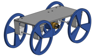
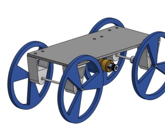
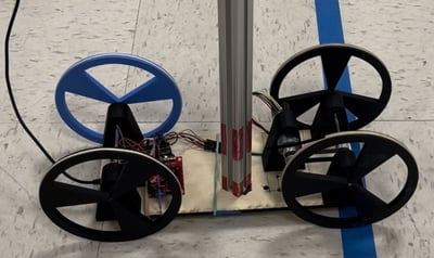
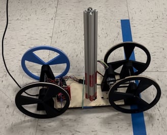

As a hardware deliverable for ME360 (Electromechanical Design), I designed a two wheel drive to transport deliveries over a set distance and route. The design covers a 5-ft distance in 7.47s. Being a motor control exercise: the machine operates on a DC motor and L298N motor driver with a 10-tooth timing belt.
Initial designs and drawings were created using SolidWorks Assembly. Physical components were supplied or printed with SLA.
Documentation of initial steps and designs can be found at the link below. Theoretical calculations can also be found below.

Skills Used:
CAD
SolidWorks Motion Analysis
Laser-cutting
3D Printing
Arduino Uno (DC Motor Control/Function)
C/C++
Circuit Design/Prototyping
Discussion:
Guideline of unsupported load created constraints on motor acceleration and linear speed. Machining limitations such as printer workspace as well as print material (SLM/PLA) need to be heavily considered (uneven prints leads to imbalanced bed for load support). A timing belt with more teeth for greater precision and accuracy.
Takeaways:
Theoretical and experimental results may differ. Theoretical maximum acceleration was greater than the experimental maximum. Future calculations for error margins.
Contributors:
Allen Fraiman
Ethan Yung
Benjamin Luu