
ME360 Motor Speed Control
Dive into motor acceleration and linear motion theory to transport a delivery to and from point A to point B across a 10 ft. distance.
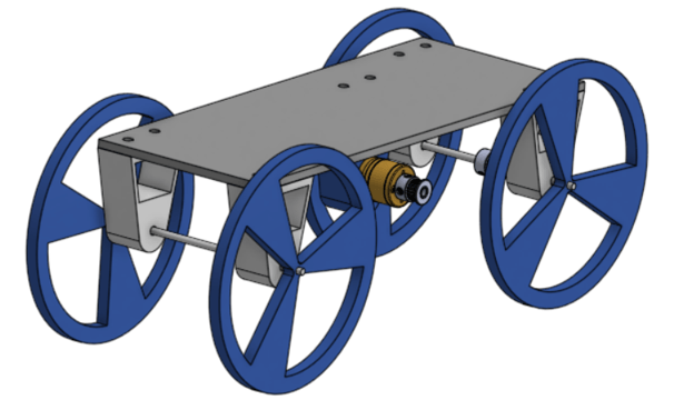
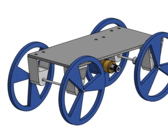
1:1 SolidWorks assembly of cart
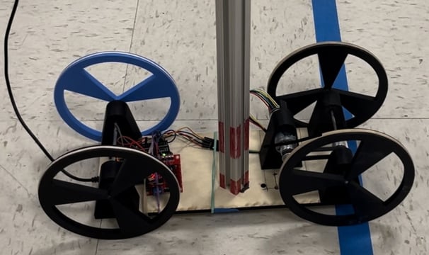
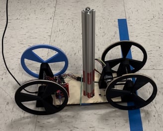
Completed physical assembly

Test Runs
The cart's theoretical maximum acceleration was calculated using the mechanical properties of the 8020 aluminum bar. Due to base friction, the vertical bar is expected to tip before sliding. Figure 1 shows the forces acting on the bar.
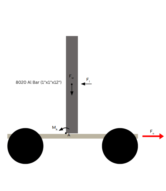
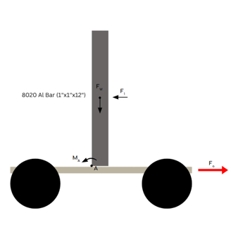
Figure 1: F_w is the resultant force of the weight of the bar. F_1 is the inertial force acting on the bar, equivalent to F_a (the force of our acceleration). M_A is the sum of the moments about point A.
From the force diagram, we can solve for the cart's theoretical maximum acceleration. Deriving from Newton's second law, the equations for analysis are shown below:
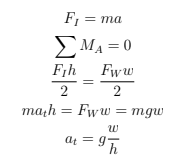
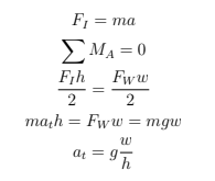
And now our calculations with the given parameters:

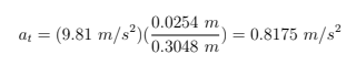
h
w
We then experiment with SolidWorks' Motion Analysis to discover the acceleration at which the net moment about point A is zero, found to be 0.8125 m/s^2. See the figures below for the simulation setup and mating conditions used to constrain the bar to the correct degrees of freedom.
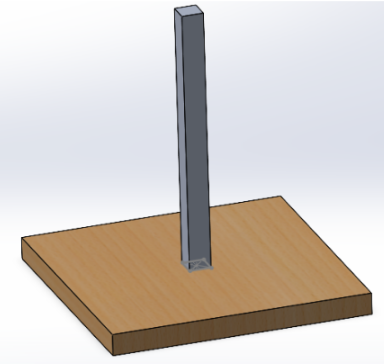
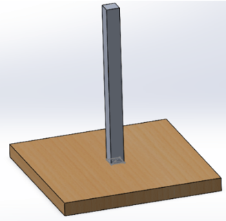
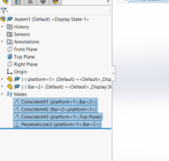

Figure 2: Platform mated to flat surface.
Figure 3: Mates shown.
Next, the simulation provides the velocity and acceleration profiles of the cart traveling in one direction at a constant acceleration followed by deceleration across the total distance.
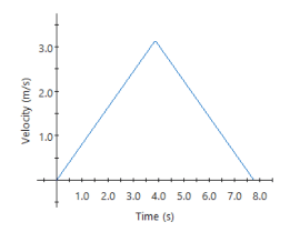
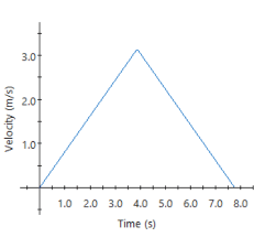
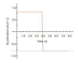
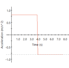
Figure 4: Velocity & acceleration profiles for the platform as a function of time, with no bar tipping observed.
From the maximum velocity, the optimal wheel radius was calculated. At the highest PWM, the DC motor reached a maximum of 320 RPM. See the calculation below:

During construction, the initially considered 3.7 in. radius was deemed unnecessary. The single DC motor likely lacked sufficient torque to drive wheels of that size effectively. Reducing the wheel size to a 2.5 in. radius also minimizes the 3D-printing time ---- a critical factor given our tight project deadline. Below, the angular velocity profiles are shown.
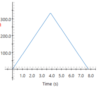
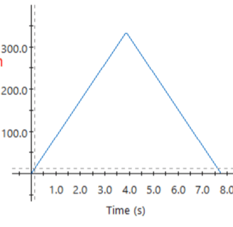
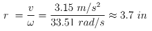
Figure 5: Maximum angular velocity profile. Maximum angular velocity is equal to 320 RPM. (Note: y-axis is in RPM)
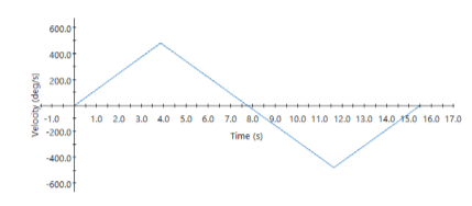
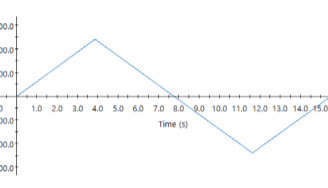
Figure 6: Practical angular velocity profile to be modeled by cart's Arduino.
Theoretical Calculations
and Simulations
Final Run
Cart reached a time of ____s. Fastest in the course.
Skills Used:
CAD
SolidWorks Motion Analysis
Laser-Cutting
3D Printing
Arduino Uno (DC Motor Control & Function)
Circuit Design & Prototyping
C/C++
Download the STL & Arduino Uno files below:
