
ME360 4 Bar Linkage Tutorial
In this project, I designed and analyzed a planar four-bar linkage system to achieve controlled, repeatable mechanical motion. Using CAD modeling (SolidWorks) and motion analysis tools, I optimized the linkage geometry to meet specific displacement, velocity, and path requirements. I validated the system’s kinematic performance through simulation and ensured manufacturability by applying proper assembly constraints, material selection, and tolerance considerations. This project demonstrates my ability to integrate mechanical design principles with computational analysis for functional motion systems.
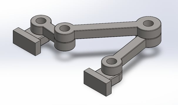
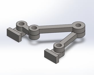
SolidWorks assembly of plain carbon steel 4-bar linkage
Trace plot of extension's midpoint
Details
The max value of the torque is -678.33 N-mm. The angle at which the max torque occurs is 158.4 degrees counter-clockwise from the crank's horizontal position. The maximum force felt by the bearings is 201.17 N. Using the equation P = r_max*omega, at max rpm of 600 , the total power required would be 42.62W. Negative torque occurs when the motor must act against the other external rotational forces (such as inertia or gravity). This ensures smooth a operation and prevents unwanted acceleration.
Skills Used:
CAD Part Design & Assembly
SolidWorks Motion Analysis
Download the STL & CSV files below: